


New Sauber Petronas Wind Tunnel takes on Formula 1 and more.
 |
| Team Principle Peter Sauber and Technical Director Willy Rampf stand in front of the 3,000 kW main fan. |
“For me, the new wind tunnel is both a technical and a marketing tool. It upgrades the Hinwil location immensely and is also meant to send a message to automotive manufacturers,” Peter Sauber commented.
The building was completed in December 2003 after a two-month calibration-phase and will start activities at the end of February 2004. The first order of business is to improve the performance of the Sauber Petronas C23 and ready it for the first European race of the Formula 1, 2004, World Championship. The first car completely developed in the new wind tunnel will be next year’s C24.
The wind tunnel will be used initially for only 2,000 hours per year, but in parallel with the formation of a new specialized personnel team, the use of the facility will gradually be extended to cover the needs of Sauber partners and sponsors and then to the automotive industry in general. Eventually the activity will be extended to 8,000 hours per year in a three-shift operation.
 |
| A scale model of a Sauber Formula 1 car is mounted to the rolling road. |
The space on the left side (ground hall and first floor) is all dedicated to marketing events. The racing teams and Sauber R&D activities related to the wind tunnel (model designers, model builders, CFD specialists and other members of the aerodynamic team) are on the remaining two floors.
The two sections are separated by a vertical glass wall that allows an impressive view of the wind tunnel, but at the same time abates the noise of the wind so that the two activities can be carried out in parallel without disturbing each other.
The task of amalgamating two completely different activities in the same building was carried out by Atelier WW of Zurich which submitted this creative proposal to Peter Sauber in 1999.
The size of the wind tunnel is such that, as well as fulfilling the aerodynamics of Formula 1 cars, it can also host sport cars and other vehicles up to the size of a van.
 |
| A full-size Sauber Formula 1 car takes to the rolling road. |
The wind tunnel itself, engineered by the German firm TLT Turbo GmbH, has a 462.5- foot loop where the air, accelerated by a 3 MW fan, can reach a speed of 186 mph.
The rolling road and the model motion system were provided by MTS Systems Corporation of Eden Prairie, Minn., said to be the number one supplier of mechanical testing and simulation systems.
The rolling road, is formed by a steel belt simulating the relative motion between the road and the vehicle, has a size that allows testing 60 percent scale models of Formula 1 cars. It can also test in a tandem mode to detect wind disturbance induced by one car following another. The model motion system is meant to suspend and control the models.
The rolling road, said to be the largest built to date, also allows testing of full size Formula 1 cars and road vehicles as previously mentioned. The whole rolling road platform can be rotated ±10 degrees to simulate the yaw effect on the vehicles.
The complete data analysis and main control system software is provided by U.K. specialist KineticaRT Ltd.
The largest diameter tube measures 30.8 feet. The single-stage axial fan, with carbon rotor blades, is driven by a 3 MW variable speed electric motor.
 |
| The air tunnel is elevated 26 feet above the ground. |
The amount of power needed to accelerate the air tends to warm up the wind circulating in the loop. To avoid such an effect and allow testing at selected air temperatures, an air conditioning section was placed before the testing section to control temperature and humidity.
The system allows performing tests at 70 degrees C with ambient temperatures up to 86 degrees F. At the exit of the plant, before the test section, the airflow is straightened by fins. The test section itself features a large crosssection (49 square feet) and a closed wall configuration that can be converted into a slotted wall configuration when testing large vehicles.
On one side a transparent wall separates the test cell from the two-store control room giving full visibility to the test team.
 |
| The compressor room is located below the rolling road. All the equipment and engineering for the air system is supplied by Kaeser Compressors of Germany. |
The compressor room is located below the rolling road. All the equipment and engineering for the air system is supplied by Kaeser Compressors of Germany.
Three screw compressors supply low pressure air to sustain the steel belt of the rolling road test platform, and another three screw compressor and a high pressure booster supply high pressure air under the wheels of the car, for the exhaust simulation and for instrument and service air. Three blowers are then used to produce the vacuum required inside the rolling road system.
“We opted for this concept for sound reasons,” says Peter Sauber. “It was important for us to build a facility that is not necessarily tied to Formula 1 use. Our facility in Hinwil will enable us to test cars up to any size including vans.”
More Stories
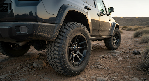
Best Wheel Size for Off-Road Adventures: What People Get Wrong
Trusted Auto Collision Repair That Restores Both Performance and Peace of Mind
What You Need to Know About Tire Pressure in Winter vs Summer