


Automating ECU testing for automotive transfer cases using HIL
In this case study from expert in modular switching & simulation tools for T&M, Pickering Interfaces, learn how its PXI fault insertion units (FIUs) helped automate ECU testing in an HIL (hardware-in-the-loop) simulation application for automotive
transfer cases, helping automotive manufacturers run more test cases in less time – and improve ECU software quality.
Testing of engine control units (ECUs), especially those that are safety-related, is as much about software testing as it is about hardware these days – mainly due to the increased intelligence required within ECUs to control braking, prevent rollovers, and ensure that power is applied to the correct wheels in a compromised driving mode. Automotive manufacturers such as Magna Powertrain, Delphi, and Continental all share similar concerns for testing the safe operation of their products. This case study explains how cost-effective, modular PXI products can be combined to create flexible test systems that automate the otherwise lengthy process of inserting faults into a system, thereby helping improve the quality of this critical automotive software. A transfer case is an electromechanical device that monitors wheel slippage and ensures that power is applied to wheels that are not slipping. As part of the design process, manufacturers run a series of tests to ensure that the software that controls their transfer cases reacts to system failures – such as open, shorted, and cross/inline resistance connections – in a predictable and safe manner.
Manufacturers sometimes develop test fixtures that allow them to manually inject faults. While this is effective, it is also time-consuming. Manual fixtures require more frequent maintenance, and this manual insertion is prone to operator error, which
can compromise test results. Pickering’s PXI fault insertion unit (FIU) switching solutions for hardware-in-the-loop (HIL) simulation applications and programmable resistors can be used to introduce electrical faults into a system, typically duplicating conditions that can occur because of corrosion, short/open circuits, and other electrical failures – caused by age, damage, or even faulty installation. By automating this fault injection process, users can run more test cases in less time, testing is more repeatable, and problems can
be identified and resolved earlier in the development cycle.
Finding faults
As part of the transfer case control mechanism (TCCM), a transfer case ECU connects to sensors and actuators in the transfer case, as well as interfaces with the vehicle’s Controller Area Network (CAN). When a driver shifts into gear, the transfer case ECU receives the command and then determines if it can perform this shift or not. After it has successfully performed a shift, the transfer case ECU reports this to the network.
In operation, many different faults can occur. For example, consider an 8-conductor cable that connects actuators and sensors in the transfer case to the control module. These connections can fail open or short to adjacent conductors; in addition, high-
resistance connections and high-resistance shorts can develop as automobiles age – and these can cause a transfer case to fail in the field. Therefore, manufacturers simulate these faults in their test lab. HIL testing has become a very popular way to test ECUs. A HIL simulator can simulate all of the inputs and outputs of a vehicle without actually having to build prototype vehicles. It can even test a transfer case ECU without needing the physical mechanics of a transfer case. In this mode, the HIL test system simulates the
transfer case, in addition to the rest of the vehicle.
To test the transfer case ECU software, designers have developed different operating scenarios. These include vehicle start-up, shutdown, and driving scenarios designed to put a transfer case control module through its paces. A typical test fixture, called a breakout box, used to manually insert faults, is shown in Figure 1.While this method is an effective way to get started, it became clear to one ofPickering’s customers that there was much room for improvement.
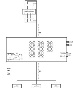
Figure 1. Generic breakout box design used for bench testing
Using the breakout box, it took this customer up to 8 minutes to run a single test case. Since the customer runs thousands of test cases, it was evident that reducing the test time was imperative. Another disadvantage of manually inserting faults in this way is that the customer could only insert shorts and opens. For thorough testing, resistive faults needed to be inserted too. Finally, breakout boxes are hard-wired, and therefore not very flexible. To test different transfer case ECUs, or different product configurations, a new breakout box is required – which is costly and time-consuming.
Automating fault insertion
Clearly, manufacturers have been thinking about how to automate fault insertion. After evaluating switching systems from multiple vendors, this customer purchased a 19-slot PXI chassis, populated with PXI bus modules (model 40-191 30A Fault Insertion Switch, shown in Figure 2), from Pickering, to simulate shorts and opens. This module is capable of carrying 40A on single channel, or 30A on all channels at the same time. It is designed to insert three different fault conditions between the test fixture and the device-under-test (DUT), including open circuits, short circuits between DUT connections, and short circuits to external signals. Solid state relays on each channel enable the test system to set signals to the DUT to open-circuit. Fault-insertion buses allow any channel to be shorted to any other channel and also enable any channel to be connected to an external signal, such as power, ignition, or ground, to simulate fault conditions.
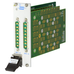
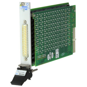
Figure 2. PXI 30A Fault Insertion Switch module Figure 3. PXI Programmable Resistor
module
Pickering’s Programmable Resistor modules (model 40-295, shown in Figure 3) are used to simulate high-resistance faults. This module provides up to 18 fully isolated variable resistors at 8-bit resolution or 10 fully isolated variable resistors at 16-bit resolution. The resistance of each of the channels can be set between 0 and 16 MΩ. Figure 4 shows how the switching system connects the HIL simulator, the transfer case ECU being tested, and the transfer case, if required. The switching system is used to inject all the potential faults. For example, to inject open faults, they simply have to open the line. To short two lines, they connect each of the two lines to a fault insertion module and connect the two signals to one of the module’s fault buses. To simulate a short to power or ground, they connect the signal line to one of the fault buses, and then connect that bus to ground or to an external voltage.
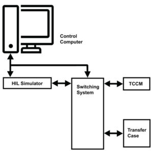
Figure 4. Switching system diagram
To inject a resistance fault into one of the signal lines running between the transfer case and the transfer case ECU, the control computer would command the switching system to switch in one of the variable resistors on the 40-295 Programmable Resistor module. Next, the resistance is varied in discreet steps: 0Ω, 5Ω, 10Ω, 20Ω, 50Ω, 100Ω, 200Ω, 500Ω, 1,000Ω, and so on until 1 MΩ is reached, or the line reacts as an open circuit.
Once a fault has been inserted, one or more driving scenarios are run, and test data is gathered. The current that the system is drawing is significant, as an unusually high current is a sure sign of problems. Other parameters considered include CAN
signals, electrical signals generated by the transfer case ECU, and overall system behavior.
By automating the fault insertion, the time taken to run a single test has been halved from 8 minutes to around 4 minutes – this is a huge saving, considering that a typical test run might include 20,000 test cases. Also, while with manual insertion, a technician had to be present all the time, now, personnel only need to be present when sensitive tests are being performed, and most tests are run overnight, unsupervised.
Interestingly, the time-savings are not necessarily used to make the test runs shorter, but to run more test cases, such as resistance faults. This is an indication of the emphasis that companies place on ECU software quality and reliability.
Analysing test results
Analysing test data is a big task. The first thing test engineers look for is whether the test has caused any damage to the DUT. No fault should damage the transfer case or the transfer case ECU, so any indication that the unit has been damaged throws up a red flag.
If none of the test cases have caused any damage, analysing the rest of the test data can proceed. Of particular interest at this point are the CAN signals and overall system behavior. In the case in point, the customer is looking for data that would indicate unintentional motor movement in a transfer case. They might also check to see that the transfer case ECU generated the appropriate diagnostic codes.
The future is automated
While the customer is pleased with the way that the Pickering switching system has allowed them to automate their test, there is more work to do. For example, instead of building separate test fixtures for each transfer case, the customer is working on a universal test system. The customer is also looking to automatically analyse the test data. An effort is also underway to reduce the number of test cases. In this customer’s case, their team thinks that they can do this by identifying test cases that are really testing the same thing and eliminating them from the test program.


More Stories
DuPont materials science advances next generation of EV batteries at The Battery Show
How a Truck Driver Can Avoid Mistakes That Lead to Truck Accidents
Car Crash Types Explained: From Rear-End to Head-On Collisions